Golf Cart Solenoid Information:
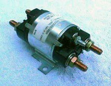
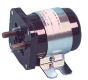
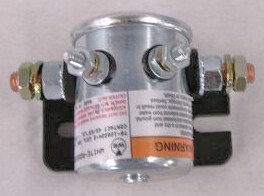
Oddly enough, to reliably conduct all this current and continue to function thousands and thousands of times, most solenoids have a relatively simple design. A steel plunger with a thick plate on one end is surrounded by a coil of thin wire wrapped many times, kind of like a fat spool of thread. When a small amount of battery juice is put across the thin wire, the magnetic field created by the coil throws the steel plunger and plate into two large bolts that stick out of the side of the solenoid case. The two large bolts, or steel studs, and the plate conduct the high current needed to power the starter or golf car motor.
The great advantage to this high amp switch is the plate throws very quickly against the large studs, thereby minimizing the electrical arcing created when connecting high amperage. Picture when you pull a plug out of the wall when the appliance is still on. You see a spark at the wall receptacle. Inside a golf car solenoid this arcing occurs every time the car is stopped and started. It's easy to see why solenoids are the #1 problem in electric cars.
In the early years of golf cars, there were all kinds and designs of multi-solenoid speed controllers. Reliably switching all the battery current required in those early years gave the manufacturers fits. Modern golf cars still have solenoids, but with the advent of electronic speed controllers and regen motors, it seems as though the solenoids do a little better these days. Today, new demands are placed on the solenoid because folks are lifting their golf cars with larger diameter tires and installing larger motors and controllers. This effectively creates the need for greater amperage draw to start the electric vehicle, to overcome inertia. These high currents also take a toll on the Forward & Reverse switch, which is designed to handle 300 amps, more or less.
Regen motor controllers now effectively function as F&R switches by electronically directing the high amperage. The regen controller needs only a low amp signal from a dash mounted F&R toggle switch to correctly switch forward or reverse. Non-regen cars do not have this function so high amperage put through to the F&R switch can create problems. In some cases, installing larger power cables in the car can alleviate F&R problems. Standard battery cable is #6. Installing #4 cable and ends can help. In severe case, a multi-solenoid F&R switch can be installed in your car to replace the mechanical rotary switch. Multi-solenoid F&R switches were common in Harleys, Columbias, Pargos, Yamahas and other early electric and gas cars. They all used a key to change directions. That's because a key switch can handle the small amount of current needed to throw a solenoid. The solenoid does the heavy lifting, so to speak.

In this design, one solenoid becomes the Forward solenoid and the other becomes the Reverse solenoid. A 10 amp, 3 way key switch controls which solenoid energizes.
Solenoids come in lots of designs with different metals used for the terminal studs and plate. Most common is copper, but years ago silver and silver plate was common. They also come in many different amperage ratings and voltage requirements needed to properly energize the coil so it functions as intended. Some solenoids are designed to work for short periods of time such as the starter solenoid in your automobile. These are intermittent duty solenoids. Golf cars require "continuous duty" solenoids because they are energized the entire time the car is under power. Auto style solenoids will work as a "continuous duty" solenoid for a while but they will prematurely fail.
Lots of things go wrong with these switches. Obviously, the high amps create a lot of arcing at the stud/plate interface inside the solenoid. Even though the plate is designed to slightly rotate with each throw, eventually the stud/plate connection deteriorates, sometimes to the point where it breaks down completely. This is evidenced by the solenoid clicking and sometimes working (car moves), and sometimes not working. Complete failure is around the corner though.
Electric cars are funny. Sometimes when there is a problem here, the failure shows up over there. Loose connections anywhere the heavy battery cables attach (i.e. –the speed switch, the motor, the batteries, F&R switch, even on the solenoids itself) creates a lot of heat build up and, if loose enough, arcing. Remember DC current is what welders use. When a sufficient air gap is established the DC arc melts steel. Solenoids and lead battery posts don't stand chance. Keep all cable connections in the car clean and tight. Inspect them at least once a year. Tightness is not as critical with the small control wires, the control circuit as it is called. Nevertheless, these connections must also be clean and tight.
Another reason solenoids don't work is because the energizing current just doesn't get to the coil. In order that electricity gets to the solenoid winding, it must first pass through the key switch and usually several small micro (or limit) switches often found on the F&R switch and on the accelerator linkage. If any of these switches have failed or if the wires interlinking them have broken or are loose, then current cannot get to the solenoid. Some of these switches are position sensitive. If one gets out of adjustment, even though it works ok, it cannot function.

The last type of solenoid failure results when the internal plate and studs freeze to each other. In other words, the solenoid works ok, but doesn't stop working when the pedal is released. This results in the car creeping on its own when the shifter is in F or R. Sticky solenoids are more common in the older resistor style cars, but this condition, if not recognized and repaired, can be a fire hazard and at a minimum, cause the battery pack to drain. Lots of folks have seen the result of a sticky solenoid. The resistor coils glow red hot, hence the fire hazard, and why this glowing condition drains the batteries. If this situation happens to you, just shift into neutral each time you stop. Get it fixed right away! Remember that arcing we mentioned earlier? Now that arcing is occurring at the F&R switch, not the solenoid. The F&R is not designed to handle this condition.
A contactor is basically an "electromagnetically driven switch" capable of carry large amounts of current. Inside the contactor are a set of fixed contacts and a set of moving contacts. When the coil is energized, a magnet either pushes or pulls a metal rod and the contacts against the current carrying components.


